1. Design on the bench
Parametric first: dimensions are parameters, not pictures. Change the mission and the machine resizes itself, in the open, with its assumptions showing. The Drone Designer is this step, live.


Machines / By the numbers
Every number on this page carries its kind: published, computed, or estimated. Nothing here is a measured result from built hardware, and the one machine that is still a design is labeled a design wherever it appears.
Two of these machines you can use in your browser right now. The third exists as a design capture, dimensioned drawings, a full parts register, and two virtual test suites, and it is presented exactly that way. That honesty is the product: a machine record you can trust is a machine record a facility can plan around.
Air / Instance 01, live
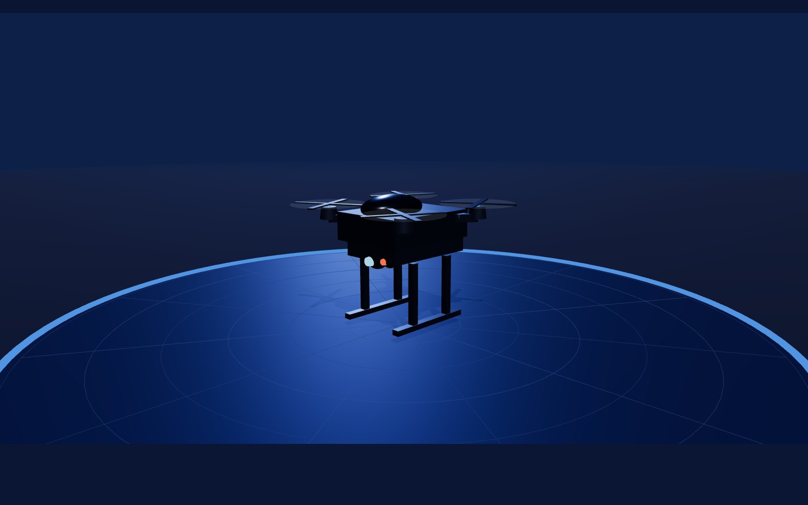
Pick the application, the climate band, the wind and sealing targets, the mission range and endurance, and the sensor payload. The bench sizes the frame class, rotor count, propeller class and battery from published component assumptions, rebuilds the airframe on the turntable while you watch, and reprices the physics on the spec card: all-up weight, endurance, mission radius, thrust-to-weight, wind limit, and an estimated unit cost.
What comes out is not a picture. It is a named configuration record, the same record the facility twins consume as a patrol unit. Five applications, seven sensor payloads, four frame classes in quad or hex. Every figure is an estimate and is labeled one on the bench itself.
The hangar / Port Twin, live
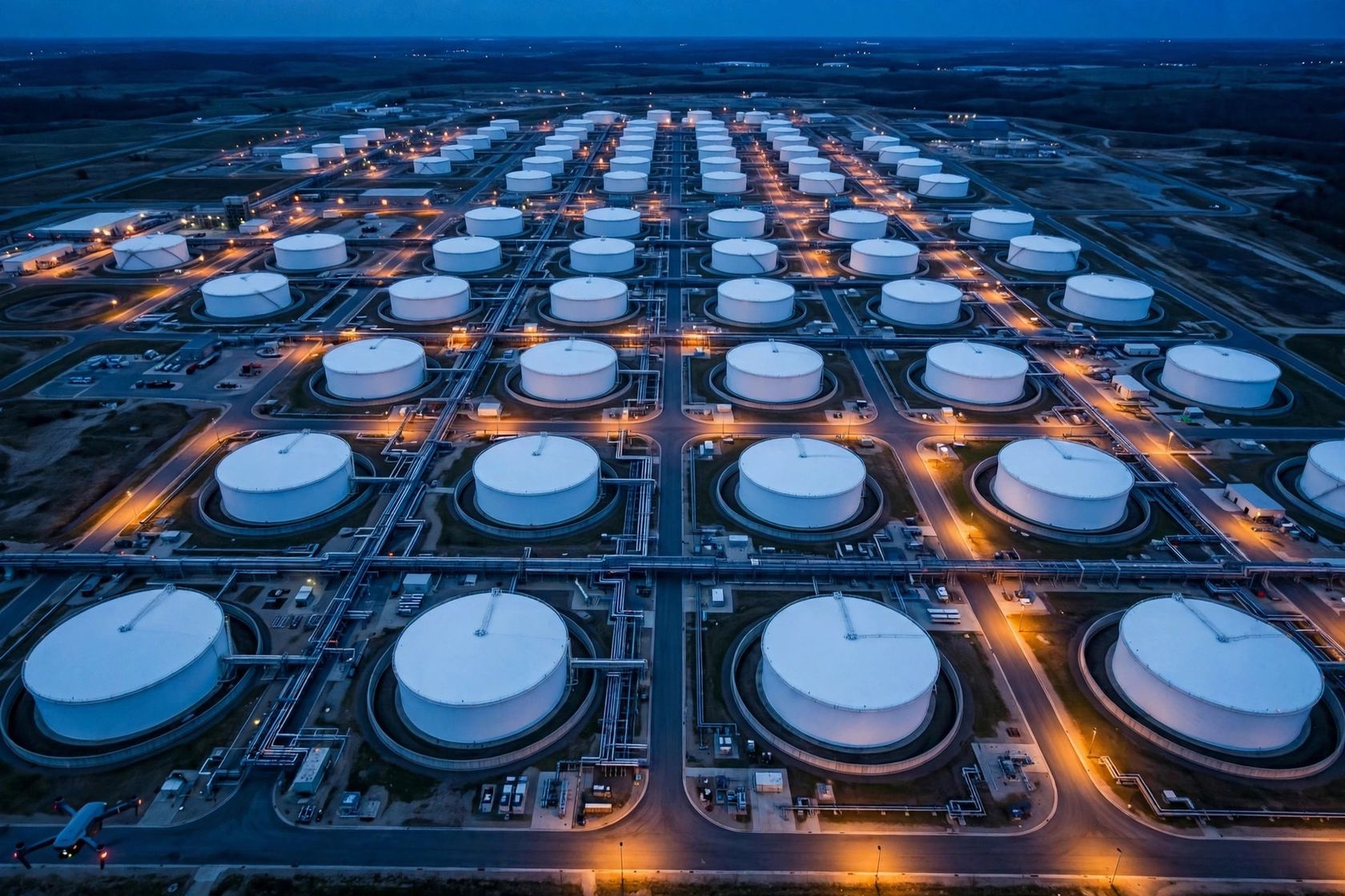
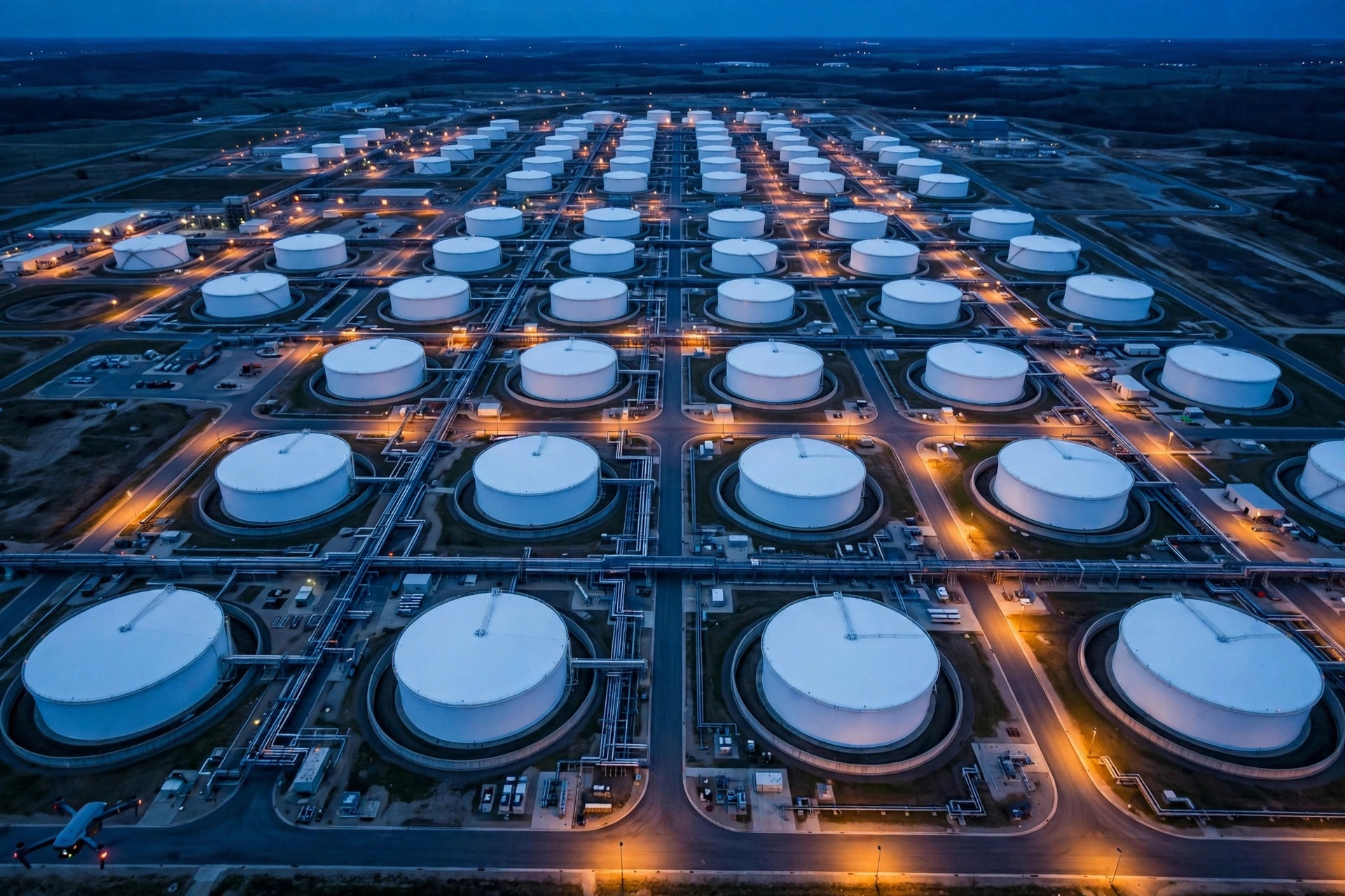
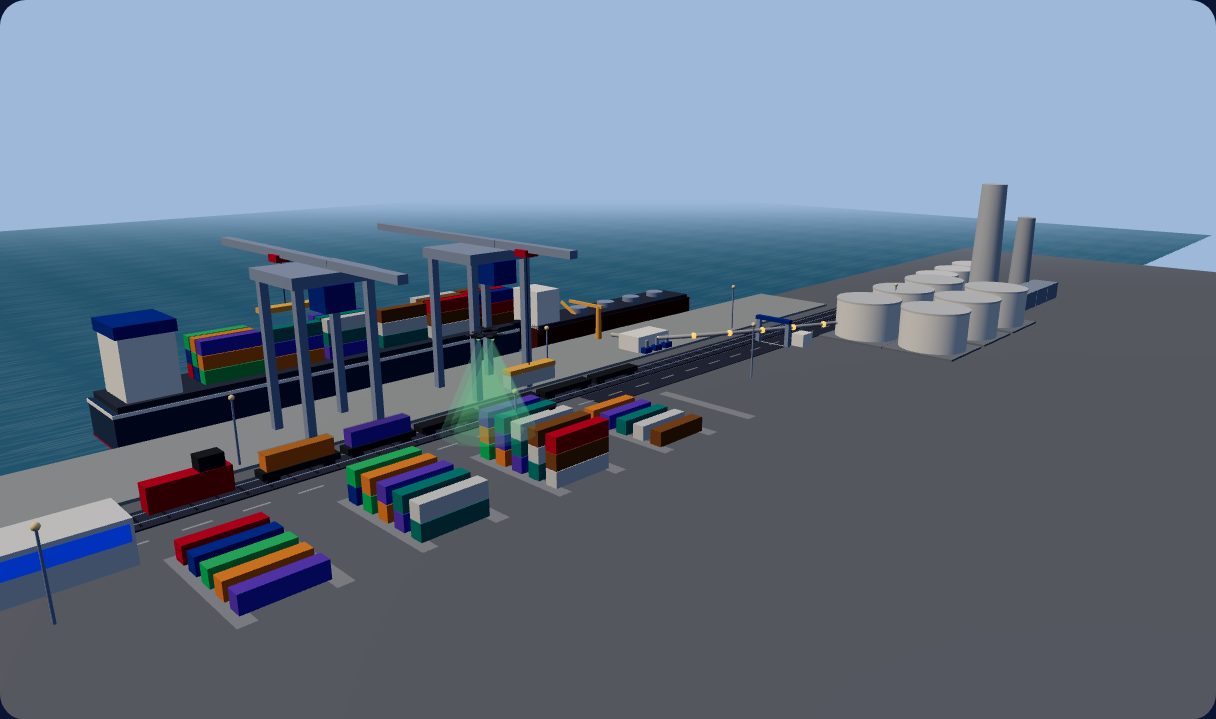
The hangar is where designed machines report for duty. Save a configuration on the bench and it spawns in the Port Twin: the same airframe, the same sensor fit, flying patrol over a working terminal model where a container ship discharges to railcars and a truck, a products tanker flows through the tank farm to a connected refinery, and a command center runs the whole operation.
This is the design loop closed in public: design a machine, hand the twin its record, watch it work. The port is a concept demonstration and every value on it is simulated and labeled as such.
Ground / Instance 02, design stage
Rail tank cars are still cleaned the hard way: a person climbs inside the car. This machine is designed to end that. It folds to pass through the car's own standard 20 inch manway, unfolds inside, and does the shoveling, spraying and scrubbing while the operator stays outside. The car is never cut, never modified: the only interfaces are the manway it was built with and the bottom outlet valve.
Four tension arms with wheels ride the shell in offset rings, extending and retracting to fit the car and to hold the machine wherever the work is. An algorithm sets arm force by task: more grip when the sprayer pushes back, more again when the shovels lean into heavy bottoms.
Two crescent shovels break up the bottoms and windrow them to the center sump and the bottom outlet, while the spray arm washes the same material ahead of the blades with steam, water and a d-limonene class solvent, so the outlet never clogs and one modest vacuum can serve the car. The scrub arm works the wall through a full circle behind them.
It sees without eyes. Optical cameras white out in steam, so awareness is layered: LiDAR for geometry, thermal imaging for the fluidization proof, radar for sludge depth through the fog, and air-purged cameras for the operator when visibility allows.
Safe by architecture. Power and intelligence stay outside on the trailer. Inside the car: fluid motors, a sealed manifold, fail-safe valves, and only low-energy intrinsically safe circuits, with trailer-side gas monitoring on a sample line and an automatic cutoff. That is the design intent, stated as intent.
The strategy is computed per car from the residue's safety data sheet, ambient conditions, the presence of a liner, the tank metal, and the disposal plan: the platform's chemistry recipe engine and steam sizing work, fed live by the machine's own sensors. Best job, least money, fastest, safest, in that order.
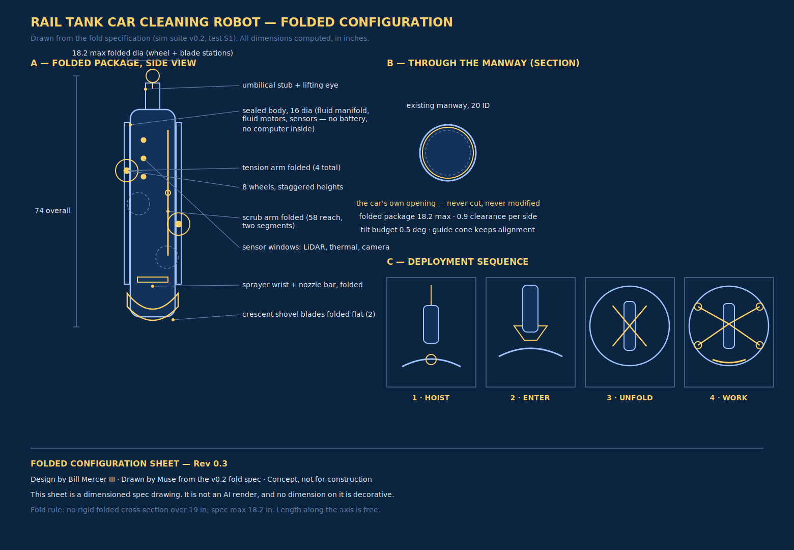
These are the numbers the design currently stands on. Each one names where it came from. When the first car is instrumented, measured values replace the computed ones, and the record will say so.
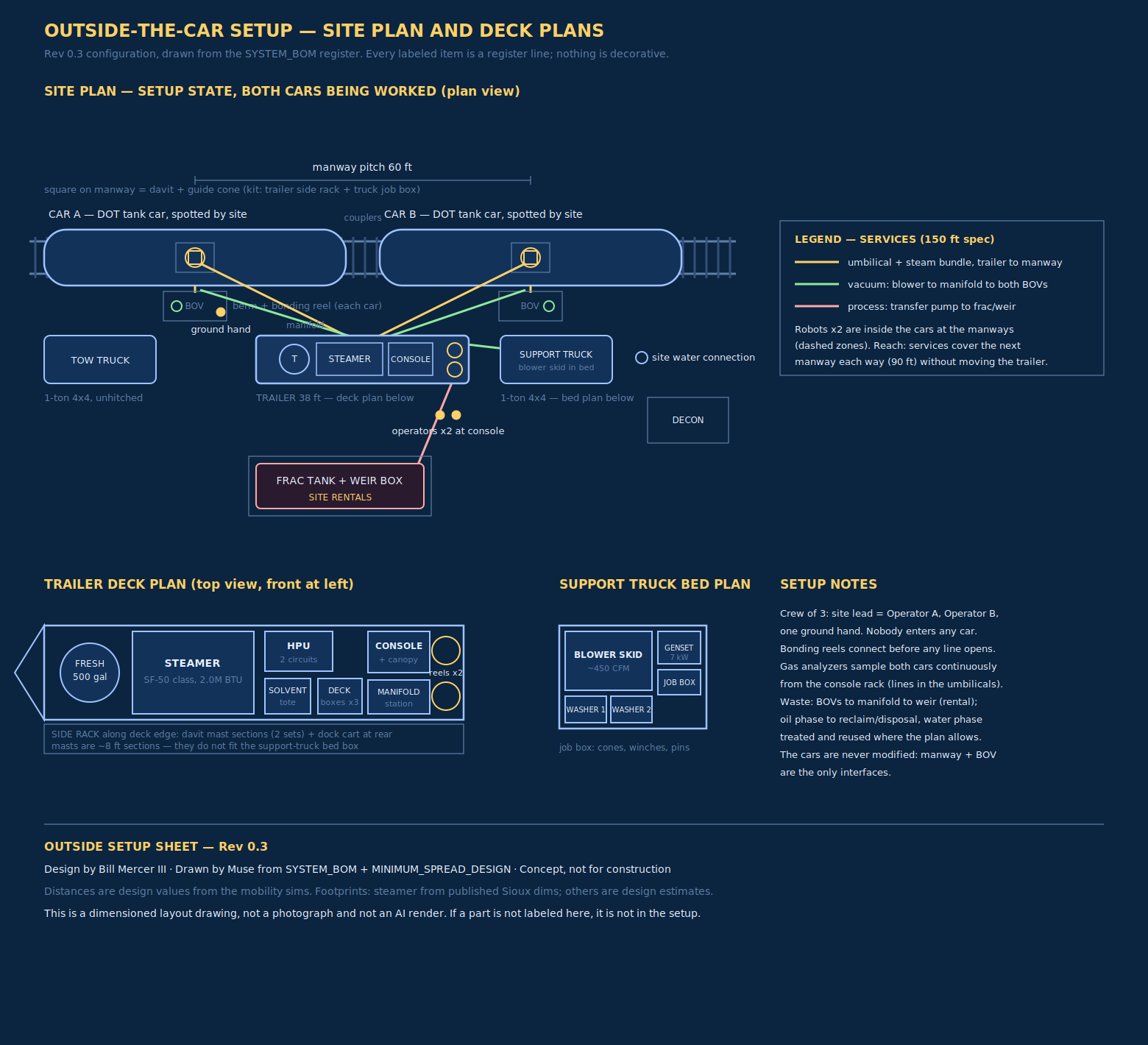
It means the design capture, the dimensioned drawings, the 174 item register, and two rounds of virtual testing exist, and nothing else does. There is no prototype to photograph, so this page shows drawings. There is no CAD release being claimed as built hardware. The honest next steps are the ones the design record itself names: instrument the first car, replace the model's anchored assumptions with measurements, and let the fold, force and thermal numbers earn their way from computed to measured.
The same record discipline that runs the twins runs this machine: every claim carries its kind, and the kind only upgrades on evidence.
The studio / How a machine gets designed here
Parametric first: dimensions are parameters, not pictures. Change the mission and the machine resizes itself, in the open, with its assumptions showing. The Drone Designer is this step, live.
Virtual test suites run the failure modes before metal does: fold clearance, force balance, thermal soak, coverage, cycle time. The railcar robot has two suites on its record, and they corrected the design twice.
The output is a configuration record the facility twin can consume, so the machine joins the fleet it will serve before it exists. Designer to Port Hangar is this step, live.
Keep reading
Start / One door
A job your crews should not have to enter, climb, or guess at. Tell us what the work is and we will show you the machine record it starts with.
Start a conversation